Proland Documentation - Core Library
Introduction
Proland is a procedural landscape rendering library. It is designed to render in real-time very large landscapes, up to whole planets. In this context it is not possible to store in GPU memory the whole landscape data. Instead this data must be produced on the fly for the current view. This can be done by loading precomputed data from disk, or by generating it with procedural methods. Another goal of Proland is the real-time editing of landscapes. This is realized by regenerating the landscape data on the fly, in the same way it is generated on the fly when the viewer moves.
Proland is made of a core library, extended by several plugins. The core library provides a producer framework, a terrain framework, and a basic user interface framework.
-
The producer framework defines a common interface for all data producers, such as CPU or GPU producers, raster data or vector data producers, etc. Producers can use other producers to produce their data and can then be composed in complex ways (for instance a terrain normal producer can produce normals from the elevations produced by an elevation producer). The producer framework also provides a generic cache component to store produced data. This is used to take advantage of the temporal coherence: thanks to this cache, a data produced for one frame can be reused for the subsequent frames.
-
The terrain framework uses a terrain quadtree that is dynamically subdivided, based on the current viewer position. It also provides a new GLSL uniform type that can be used to access a cache of raster data on GPU, and some methods to update these caches (by using data producers) and to draw a terrain. It also provides deformations to map a flat terrain to other shapes, such as spheres (to render planets).
- the user interface framework is based on EventHandlers. It provides the basics for navigating through the large scenes that you can display in Proland.
The Proland plugins provide several predefined producers based on this framework: some producers are dedicated to the production of terrain elevation data, others are designed to produce generic raster data (this data can represent anything you want, such as reflectances, land cover classes, normal maps, horizon maps, ambient occlusion maps, etc), and others produce vector data (it is also possible to produce raster data from vector data, by rasterizing the vector data into textures).
Proland is based on the Ork library in several ways:
-
the producer framework uses Ork tasks to produce data. Hence the landscape data can be produced in parallel, or even ahead of time with the prefetching feature of the Ork scheduling framework. This framework also provides the dependencies between producer tasks. Hence when a data produced by a producer is edited, all the data derived directly or indirectly from it, via other producers, is also automatically recomputed.
-
the terrain framework uses the Ork rendering framework for shaders, meshes, etc. and extends the Ork scene graph with new methods to update GPU caches and to draw terrains.
- finally Proland extends the Ork resource framework with new resource types for the predefined producers and for the terrain components.
The following sections present the producer framework, the terrain framework and the user interface framework:
Producer framework
The producer framework defines how the landscape data is produced, stored and cached. Using this framework it is possible to define several producers, each producer producing a part of the landscape data. For instance there can be a producer for the terrain elevation, another for the terrain normals, a producer for the terrain reflectance, another for the river data, a producer for building models, etc. Each producer can use as input procedural parameters, data stored on disk, data produced by another producer, a combination of these, etc.
The producer framework assumes that the data produced by a producer is divided in a quadtree. This means that each tile, i.e., the data associated with a quad, can be produced independently. A tile can contain raster data, vector data, or any other data. Each producer can organize its data using its own quadtree, i.e., the quadtrees of the various producers need not have the same characteristics (maximum depth, tile size, etc). However the quads and tiles are always identified using the same "coordinate system", whatever their quadtree. In fact a quad or tile is identified by its level in the quadtree (0 is the root), and by its tx,ty coordinates at this level (tx and ty varying between 0 and 2level-1 with 0,0 being the lower left corner). These (level,tx,ty) coordinates are called logical coordinates:
The root tile (0,0,0) of a producer contains the data corresponding to the whole landscape, at a coarse resolution. The tiles at the other levels contain only a part of the data, but at higher resolution (the higher the level, the higher the resolution). The producer framework also uses physical coordinates. These coordinates are the ox,oy coordinates of the lower left corner of a quad in a fixed reference frame, whose origin is at the center of the root quad, plus the size of the quad l in some length unit (e.g., meters). The figure below illustrates this, assuming that the size of the root quad is L:
These physical coordinates are only local coordinates, like the local reference frame of each scene node in an Ork scene graph. At rendering time the landscape can be placed anywhere in the world frame with appropriate translations, rotations and other transformations.
- Note:
- there is a clear distinction between a quad and a tile. A quad is a node in a quadtree, a tile is some data associated with a quad. Logical coordinates apply to both quads and tiles, but physical coordinates are only associated with quads. In fact a tile can contain data outside the physical boundary of its associated quad. In this case we say that the tile has a non empty border. Tiles with borders introduce some redundancy in the produced data, but this redundancy is sometimes useful to avoid artifacts with texture filtering, to avoid producing neighboring tiles, etc. The figure below illustrates this difference with tiles containing raster data.
Tiles are stored in tile storages. There are tile storages for raster data tiles on GPU (using textures), tile storages for raster data on CPU (using arrays), and tile storages for vector data or other CPU data (using ork::Object). It is also possible to define tile storages on GPU using GPU buffers, for instance vertex buffers (for instance the PlantsProducer produces one point mesh for each quad, with all these meshes stored in a single GPU buffer - see the source code of proland::PlantsProducer).
A tile storage can contain tiles produced by several producers. In other words several producers can use the same storage to store their tiles. A tile storage can contain tiles that are necessary for the current view, but it can also contain tiles that were created for a previous frame but are no longer used. If the viewer goes back to the previous viewpoint, then these tiles will be reused directly: they will not need to be produced again. Similarly a tile storage can contain tiles that are prefetched, i.e., that are produced ahead of time for future frames.
The knowledge of which tiles are in use, i.e., necessary for the current view, and which are not (cached from a previous frame, or prefetched for a future frame), is managed by a tile cache. A tile cache also stores a mapping between the logical coordinates of tiles, and their storage coordinates, i.e., their location in the tile storage. Like tile storages, tile caches can be shared between tile producers. The figure below illustrates the relation between a tile cache and a tile storage, using a GPU tile storage (the storage coordinates format and meaning depend on the kind of storage used. For a GPUTileStorage using textures, it is a layer index - the storage texture is a 2DArrayTexture, with one tile per layer).
In this example, the tile cache indicates that the tiles (2,1,2) and (2,1,3) are in use, and are stored in the tile storage, in the layers 3 and 1. It also indicates that 3 other tiles are available in the tile storage but are currently unused, i.e., not necessary for the current view. The tile storage stores the tiles in a 2D texture array with 7 layers. Each layer is a 8x8 2D texture, also called a slot. Currently only 5 slots are allocated, the remaining slots are free to store other tiles. Note that an allocated slot (at the storage level) can correspond to an unused tile or to a tile in use (at the cache level).
Tile storage
A tile storage is represented with the proland::TileStorage class. This abstract class has 3 sub classes proland::GPUTileStorage, proland::CPUTileStorage and proland::ObjectTileStorage, for GPU raster data, CPU raster data, and CPU vector or other data (respectively - you can also implement your own subclass, see for instance the source code of proland::PlantsProducer, which defines a GPU tile storage based on a vertex buffer object). Each tile storage has a capacity which is the number of slots in this storage, each slot being able to store one tile. The capacity of a storage is fixed and cannot be changed at runtime. Each slot can either be free or allocated. A free slot does not contain any tile, an allocated slot contain a single tile (either in use or not).
The capacity can be retrieved with proland::TileStorage::getCapacity. The number of free slots is given by proland::TileStorage::getFreeSlots. A free slot can be obtained with proland::TileStorage::newSlot. The returned slot is then considered allocated, and can be used to store a tile. Conversely an allocated slot can be returned to the pool of free slots with proland::TileStorage::deleteSlot.
GPUTileStorage
The proland::GPUTileStorage is a tile storage to store raster data tiles on GPU. It uses 2D textures or 2D array textures to store the tiles. Such a tile storage can be created with the Ork resource framework, using the following format:
<?xml version="1.0" ?>
<gpuTileStorage name="myGpuStorage"
    tileSize="196" nTiles="512"
    internalformat="RGBA8" format="RGBA" type="UNSIGNED_BYTE"
    min="LINEAR_MIPMAP_LINEAR" mag="LINEAR" minLOD="0" maxLOD="1"
    tileMap="false"/>
In this example each slot is created to store tiles made of 196x196 pixels (this size must include the tile borders, if any). The total number of slots is 512. In other words this storage allocates a 196x196x512 2D array texture. This texture uses the RGBA8 internal format (this gives a total of 71.2 MB). The texture filters and min and max LOD are specified like for texture resources. The tileMap attribute in explained in the terrain framework section.
The slots managed by a GPU tile storage are described with the proland::GPUTileStorage::GPUSlot class. This class describes the location of the slot in the storage textures. It also provides methods to copy a part of the framebuffer or of a texture into this slot.
- Note:
- If you use a mipmap filter, then each time the content of a slot is changed you must call proland::GPUTileStorage::notifyChange (this is used to automatically update the mipmap levels of the storage textures when changes have occurred). In fact you don't have to do this yourself, unless you write your own producer.
CPUTileStorage
The proland::CPUTileStorage is a tile storage to store raster data tiles on CPU. It uses arrays to store the tiles (each tile is stored in its own array). Such a tile storage can be created with the Ork resource framework, using the following format:
<?xml version="1.0" ?>
<cpuByteTileStorage name="myCpuStorage"
    tileSize="196" channels="4" capacity="1024"/>
In this example the storage can store 1024 tiles made of 196x196 pixels, with 4 bytes per pixel. Using cpuFloatTileStorage instead, the pixels would have been made of 4 floats per pixels.
The slots managed by a CPU tile storage are described with the proland::CPUTileStorage::CPUSlot class. This class gives access to the array containing the tile raster data.
ObjectTileStorage
The proland::ObjectTileStorage is a tile storage to store arbitrary data tiles on CPU. Each slot stores a pointer to an ork::Object. Unlike the GPU and CPU tile storages, here the data for each slot is not allocated by the tile storage (since it can be arbitrary). Instead, you must allocate this data manually each time you get new slot, and you must delete it manually each time you delete a slot. Such a tile storage can be created with the Ork resource framework, using the following format:
<?xml version="1.0" ?>
<objectTileStorage name="myObjectStorage" capacity="1024"/>
The slots managed by an object tile storage are described with the proland::ObjectTileStorage::ObjectSlot class. This class gives access to the tile data via a pointer.
Tile cache
A tile cache is represented with the proland::TileCache class. Since a tile cache does not store tiles itself (this is done by tile storages), but only stores and manages a mapping between logical tile coordinates and slots in a tile storage, a single class can be used for all kinds of tiles.
A tile cache has an associated tile storage. It manages a mapping between logical tile coordinates and slots in its associated storage. A tile cache is used by one or more tile producers. Each time a tile producer is created and associated with a tile cache, it gets a local producer id from the tile cache, and the tile cache maintains a reference to this producer. This reference is used when a new tile from this producer is requested from the cache, in order to produce it.
The tiles managed by a tile cache can be in use or not (tiles in use generally correspond to those that are necessary to render the current landscape view). More precisely a tile cache keeps track of the number of users of each tile. Users acquire tiles with the proland::TileCache::getTile method, and release them with proland::TileCache::putTile. Hence the first method increments the counter of users of the requested tile, and the second method decrements this counter. When this counter becomes 0 the tile becomes unused.
A tile in use is "locked", i.e., its slot in the tile storage cannot be reused to store another tile, as long as the tile is in use. On the contrary, a unused tile can be evicted from the cache at any moment, and its slot can be reused to store another tile. This happens, in particular, when a new used tile is needed, but all slots in the storage are allocated. Then it is necessary to evict an unused tile from the cache, in order to reuse its slot to store the new used tile. An evicted tile will need to be produced again if it is needed again in the future. In order to minimize the number of times a tile is regenerated, a tile cache evicts in priority the tiles that have not been used since a long time (this heuristic is called the Least Recently Used - or LRU - cache heuristic).
In addition to getTile and putTile, the main methods of a tile cache are the following:
-
the proland::TileCache::findTile method can be used to find a tile in the cache. This method does not change the number of users of the returned tile. The tile can be looked for in the list of tiles that are in use, or in all the tiles managed by the tile cache, whether they are used or not.
-
the proland::TileCache::prefetchTile method is used to request the production of a tile for the future frames. The method returns immediately. The tile will be created as an unused tile. If there is no free slot to store this prefetched tile, an unused tile will be evicted first.
- the proland::TileCache::invalidateTiles method is used to force the regeneration of the tiles produced by a given producer. All the tiles keep their current slot in the tile storage, but the slot content will be recomputed before use (this means that tiles in use will be recomputed immediately, while unused tiles will not be recomputed before they become in use again).
When a tile is requested with getTile two cases can happen:
-
if the tile is in cache its number of users is incremented by one. If the tile was unused it becomes in use.
- otherwise the tile is produced, in a free storage slot or in the slot of a previously evicted (and unused) tile. In fact the tile is not produced immediately. Instead a ork::Task to produce the tile is returned (inside a proland::TileCache::Tile). This task needs to be executed by a ork::Scheduler before the tile data can be used.
TileCache resource
A tile cache can be loaded with the Ork resource framework, using the following format (the nested storage resource can of course be a cpuXxxTileStorage or an objectTileStorage; it describes the tile storage associated with the tile cache):
<?xml version="1.0" ?>
<tileCache name="myCache" scheduler="myScheduler">
    <gpuTileStorage .../>
</tileCache>
Tile producer
A tile producer is represented with the proland::TileProducer class. This abstract class has many concrete sub classes, presented in the sec-producers section. A tile producer has an associated tile cache, used to cache the tiles it produces (it is given by proland::TileProducer::getCache). A tile producer is associated with a single cache, but a cache can be used by several producers (if they produce tiles of the same type). In order to distinguish tiles produced by different producers in a tile cache, each producer has a unique local identifier in this cache, automatically assigned when the producer is created. It is given by proland::TileProducer::getId.
The main method of a tile producer is the proland::TileProducer::doCreateTile abstract method. It implements the tile production algorithm, i.e., it defines how the tiles are produced. However this method is never called directly, but through the proland::TileProducer::getTile method. If a requested tile is not in the cache, getTile does not produce this tile immediately. Instead a ork::Task to produce this tile is returned.
A "basic" tile producer returns a "basic" ork::Task to produce a tile, i.e. a task without dependencies on other tasks. On the contrary, a tile producer that uses as input data tiles produced by another producer returns a ork::TaskGraph to produce a tile. This task graph contains the task to produce the tile, with dependencies to the task(s) that produce the input data. Consider for example a normal producer, producing terrain normals from terrain elevations produced by an elevation producer. We then have the following producers, caches and storages:
Then the task graphs returned by the getTile method of the normal producer look like this:
The task N(2,1,2) to produce the normal tile (2,1,2) has a dependency towards the task E(2,1,2) that produces the elevations for the same quad, and both are put in a task graph.
In practice the elevation producer is not a "basic" producer: it uses as input data tiles produced by a residual producer (see sec-producers). It also uses itself recursively: in fact an elevation tile is produced from its parent elevation tile, by upsampling its data and adding to it residual elevations. An elevation producer may also use vector data produced by a graph producer (via layers - see below), which also uses itself recursively. So in fact we have the following relations between the normal, elevation, residual and graph producers (here we do not show the associated caches and storages):
The task N(2,1,2) to produce the normal tile (2,1,2) is then a more complex task graph (in reality the graph is even more complex, because a normal producer also uses itself recursively, like the elevation and graph producers):
At the highest level we still have a task graph with two nested tasks N(2,1,2) and E(2,1,2), with a dependency between them, as in the previous example. Here however the E(2,1,2) task is itself a task graph. Note the "fractal" aspect of the whole graph: this comes from the recursive use of the elevation producer by itself, and of the graph producer by itself. Note also that this double recursion leads to tasks that appear in several task graphs, i.e., that are shared between task graphs (there is only one instance of each shared task).
Successive calls to the getTile method for the same tile, always return the same ork::Task instance. Since a task instance is executed only once (see Task graph), the complex task graph above, once scheduled, will generally not lead to the execution of all the tasks it contains. Indeed most tasks will probably have already been executed, and so will not be reexecuted. However, if any task in this graph is explicitly rescheduled (this happens if the corresponding tile is invalidated with proland::TileProducer::invalidateTiles), the Ork framework will automatically reschedule the tasks that depend directly or indirectly on the rescheduled task. Hence all the tiles depending directly or indirectly on the invalidated tile will be automatically recomputed.
Main methods
The proland::TileProducer class provides some generic methods that provide information about the tiles it can produce:
-
the proland::TileProducer::isGpuProducer indicates whether this producer produces raster data tiles on GPU or not. A GPU producer is supposed to use a tile cache associated with a proland::GPUTileStorage.
-
the proland::TileProducer::getRootQuadSize gives the physical size of the root quad of the quadtree managed by this producer. This size can be set with proland::TileProducer::setRootQuadSize.
-
the proland::TileProducer::getBorder method indicates if the tiles produced by this producer have a border. More precisely it indicates the size of these borders, in pixels (assuming that tiles contain raster data). The default implementation of this method returns 0 (i.e., no border), but you can override it.
-
the proland::TileProducer::hasTile method indicates if this producer can produce a tile, specified by its logical coordinates. By default this method returns always
true, but you can override it. For instance, it is common for producers to be limited to a maximum resolution, i.e., to a maximum level in the quadtree. -
the proland::TileProducer::hasChildren method indicates if this producer can produce the sub tiles of a tile, specified by its logical coordinates. The producer framework assumes that if a sub tile of a tile can be produced, then the four sub tiles of this tile can be produced. Hence this method returns
trueif the lower left sub tile of the specified tile can be produced (as returned by hasTile).
There is also a proland::TileProducer::update method, which is called once per frame (via proland::UpdateTileSamplersTask and proland::TileSampler::update). This method does nothing by default, but you can override it to invalidate the tiles if necessary (i.e., if some input data used to produce the tiles has changed - if this input data is produced by another producer then you don't need to do this, it will be done automatically via the Ork tasks framework). Alternatively, if the produced data must be animated, you can also modify, via this method, the content of already produced tiles at each frame.
Finally the proland::TileProducer class also provides some convenient methods that simply call the corresponding methods on its associated tile cache. These methods are:
- proland::TileProducer::getTile
- proland::TileProducer::putTile
- proland::TileProducer::findTile
- proland::TileProducer::prefetchTile
- proland::TileProducer::invalidateTiles
Tile producer layers
Some tile producers can be customized with layers. A layer can modify the data produced by the "raw" producer or by the previous layers. For instance you can imagine a layer to draw roads from vector data on top of a satellite photo (the "raw" data), or a layer to modify the terrain elevations, based on the same road vector data, to generate the footprint of roads in the terrain. Like a producer, a layer can use as input data produced by other producers (in the previous example, the layers use vector data produced by a graph producer). The layers of a tile producer are managed with the proland::TileProducer::getLayerCount, proland::TileProducer::getLayer and proland::TileProducer::addLayer methods.
User defined producers
You can define your own tile producers by extending the proland::TileProducer class. This section shows how you can do this, using the example of a GPU producer using as input tiles produced by a CPU producer.
class MyProducer : public TileProducer
{

public:
    MyProducer(Ptr<TileCache> cache, Ptr<TileProducer> input, ...) :
        TileProducer("MyProducer", "MyCreateTile")
    {
        init(cache, input, ...);
    }

    virtual ~MyProducer()
    {
    }


protected:
    MyProducer() : TileProducer("MyProducer", "MyCreateTile")
    {
    }

    void init(Ptr<TileCache> cache, Ptr<TileProducer> input, ...)
    {
        TileProducer::init(cache, true);
        this->input = input;
        ...
    }
The above code contains the initialization code to create our producer, using the pattern to easily define an Ork resource subclass of this class (see User defined resources). The constructor takes as argument a tile cache, that will be used to cache the produced tiles. This argument is required by the constructor of the super class. The constructor also takes as argument the producer whose tiles will be used as input. We assume it is a CPU producer.
    virtual Ptr<Task> startCreateTile(int level, int tx, int ty,
        unsigned int deadline, Ptr<Task> task, Ptr<TaskGraph> owner)
    {
        Ptr<TaskGraph> result = owner == NULL ? new TaskGraph(task) : owner;
        TileCache::Tile *t = input->getTile(level, tx, ty, deadline);
        result->addTask(t->task);
        result->addDependency(task, t->task);
        return result;
    }
The startCreateTile method overrides the corresponding method of the super class. Its role is to construct the task or graph of tasks to produce a given tile. Here our producer use as input a tile produced by another producer, so the "basic" task to produce our tile - automatically constructed and passed as argument in task - must have a dependency on this input task (so that it is executed before we start producing our tile). This is why this method creates a task graph containing task, as well as the task t to produce the input. Its then adds these tasks in a task graph, and creates a dependency between them. Note that t is obtained with a getTile: this will lock this input tile until we call putTile, i.e., the input data will not be evicted from the cache unexpectedly.
    virtual bool doCreateTile(int level, int tx, int ty, TileStorage::Slot *data)
    {
        CPUTileStorage<unsigned char>::CPUSlot *in;
        GPUTileStorage::GPUSlot *out;
        TileCache::Tile *t = intput->findTile(level, tx, ty);
        in = dynamic_cast<CPUTileStorage<unsigned char>::CPUSlot*>(t->getData());
        out = dynamic_cast<GPUTileStorage::GPUSlot*>(data);
        ...
        getCache()->getStorage().cast<GPUTileStorage>()->notifyChange(out);
    }
The doCreateTile method overrides the corresponding method of the super class. Its role is to generate the requested tile. Here this method first gets the input tile needed for this production. Note that is does so with findTile: we are sure the tile is in cache because it can not be evicted until we call putTile (see above). It then gets the slot in which the tile must be produced. This slot is passed as argument in data but must be cast to the right type. Once the tile is produced (by the "dots"), the producer notifies its tile storage that the slot in which the tile has been produced has changed, so the mipmap levels of the storage textures can be automatically updated when needed (see GPUTileStorage).
    virtual void stopCreateTile(int level, int tx, int ty)
    {
        TileCache::Tile *t = input->findTile(level, tx, ty);
        input->putTile(t);
    }

private:
    Ptr<TileProducer> input;
};
The stopCreateTile method overrides the corresponding method of the super class. Its role is to clean up the "resources" used during the tile production. Here this method calls putTile on the tile used as input, since the content of this tile is no longer necessary. The effect of this call is to unlock this input tile (if it was not locked by other users), which can then be evicted from its cache at any moment.
User defined tile producer layers
You can also define your own tile producer layers by extending the proland::TileLayer class. This task is very similar with the definition of a tile producer. In particular a tile producer layer has the same startCreateTile, doCreateTile and stopCreateTile methods, which have the same role and can be overridden in the same way.
Terrain framework
The terrain rendering framework manages one or more terrains, each terrain being associated with a set of tile producers. For each terrain, the terrain quadtree is dynamically subdivided, based on the current viewer position. When new quads are subdivided, the producers associated with the terrain are used to produce the corresponding tiles. The terrain framework also provides new GLSL uniforms that allow shaders to access the slots of a texture cache like a normal texture. Hence you can access the produced tiles like normal textures in your shaders. Finally the framework provides deformations to map a flat terrain to other shapes, such as spheres (to render planets).
- Note:
- here we speak about "terrains" but in fact the framework is not limited to the terrain itself. Indeed the tile producers associated with a terrain can produce any kind of data, including data to render 3D vegetation or buildings on top of the terrain (see the "trees1" example). Hence the "terrain" framework can be used to render full landscapes.
Terrain deformation
The terrain framework supports terrain deformations. A deformation here is not a local terrain modification. Instead, it is a global deformation of space, which can for instance transform a plane into a sphere or a cylinder. Terrain deformations are used to generate spherical planets, cylindrical terrains (e.g., for a cylindrical space ship whose rotation simulates gravity), etc.
A deformation transforms a point in a local space into a point in a deformed space:
In practice the local space is the space in which the quad physical coordinates are defined - see Producer framework. In the local space the "sea level" surface is the plane z=0, z being the vertical axis. This plane can be deformed into a sphere, a cylinder, etc. Note however that a deformation transforms the whole 3D space, not a single 2D surface (this is needed to transform points above the sea level).
The proland::Deformation class represents a terrain deformation. It defines the methods that a terrain deformation must provide, and implements them for the case of the identity deformation (i.e., no deformation). The proland::SphericalDeformation is a sub class of this class that deforms horizontal planes into spheres. Finally the proland::CylindricalDeformation is a sub class of this class that deforms horizontal planes into cylinders. Note that you can define your own sub classes if needed.
The actual deformation is implemented by the following methods:
-
proland::Deformation::localToDeformed: transforms a point in the local space into the deformed space.
-
proland::Deformation::deformedToLocal: transforms a point in the deformed space into the local space.
-
proland::Deformation::localToDeformedDifferential: computes the differential of the deformation function at some local point. This differential gives a linear approximation of the deformation around a point: if p is near localPt, then the deformed point corresponding to p can be approximated with
localToDeformedDifferential(localPt) * (p - localPt). - proland::Deformation::deformedToTangentFrame: computes an orthonormal reference frame of the tangent space at a deformed point. This reference frame is such that its xy plane is the tangent plane, at deformedPt, to the deformed surface corresponding to the local plane z=cste. This orthonormal reference frame does not give the differential of the inverse deformation function, which in general is not an orthonormal transformation. This tangent frame defines the tangent space in which terrain normals are computed.
The proland::Deformation class is also responsible to set the GLSL shader uniforms that are necessary to transform the terrain vertices on GPU. This is done with the proland::Deformation::setUniforms methods. There are two such methods: the first one can set uniforms that do not depend on a quad (such as a sphere radius for a spherical deformation), while the other can set uniforms that are specific to a quad. The GLSL uniforms that are set by these methods depend on the actual transformation.
Spherical deformation
The proland::SphericalDeformation deforms horizontal planes into spheres. It is intended to render planets of radius R (at sea level), using 6 terrains placed on the faces of a cube of size 2R x 2R x 2R, each terrain being deformed into a portion of the sphere:
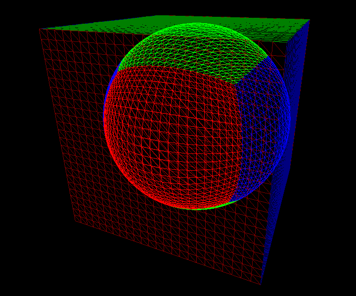
Mathematically, the deformation is defined as follows: from a point p=(x,y,z) in local space, we first construct the point P=(x,y,R) on the "top" (i.e., "north") cube face (in green in the above figure), in the planet frame (a reference frame whose origin is the planet center). This point is then used to define the deformed point, in the planet frame, as q=(R+z) P / ∥ P ∥:
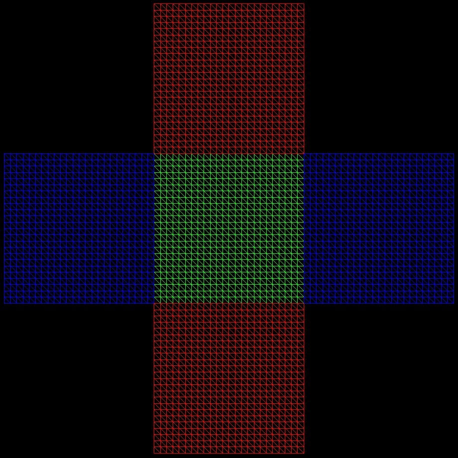
This deformation maps the plane z=0 into a half-sphere. Hence at least two terrains are needed to cover the whole sphere. In order to limit deformations, it is better to use 6 terrains on the face of a cube, as shown above. The inverse deformation maps the whole sphere, except the south pole "face", to a developed cube in a plane (like for a cube map - see above figure). For the "north" face, the inverse deformation is:
The tangent frame at some deformed point q, in which terrain normals are computed, is defined by the following unit vectors in planet frame:
ux = (0,1,0) × uz / ∥ (0,1,0) × uz ∥ |
uy = uz × ux |
uz = q / ∥ q ∥ |
GLSL uniforms
In theory the transformation q = (R+z) P / ∥ P ∥ can be easily implemented on GPU. There are however two precision problems, even with 32 bits floats. They are linked to the fact that transformed points are computed in a reference frame whose origin is at the planet center. Hence for a planet like the Earth, the coordinates of transformed points are large (of the order of R=6360000m) and do not have enough bits left to represent the altitude precisely. The other problem is when these coordinates are transformed into the reference frame of the camera, whose origin must also be expressed in the planet frame (subtracting two large numbers close to each other leads imprecise results).
In order to solve these two problems, the idea is to compute the deformed quad corners and to transform them in the camera frame on CPU, using double precision. The result are points with "small" coordinates, that can easily be interpolated on GPU without precision problems. More precisely we compute on CPU the deformed quad corners ci (i=1,...4) and the vertical vectors ni at these corners, in the camera frame, and we use them on GPU. The idea is to compute a deformed vertex as an interpolation of the deformed corners, displaced along an interpolation of the vertical vectors:
We note pi the corners of a quad in the local space, and ci the corresponding deformed points (ci = R Pi / ∥ Pi ∥, where Pi = (pix,piy,R) in the planet frame). We also note ni the deformed vertical vectors (ni = P i / ∥ Pi ∥ in the planet frame). We want to compute the deformed point corresponding to a local point p defined as p= ∑ αi pi + (0,0,h) (with ∑ αi = 1). And we want to express this deformed point q as
Finally we want that ∑ α'i = 1 so that the above formula holds in any reference frame. The unknowns α' i and h' can be computed by writing the above relation in the planet frame, and by comparing it with the definition of q in this frame, q = (R+h) P / ∥ P ∥:
q = ∑ α'i ci + h' ∑ α'i ni = (R + h') ∑ α' i Pi / ∥ Pi ∥ |
q = (R + h) P / ∥ P ∥ = (R + h) ∑ α i Pi / ∥ ∑ αi Pi ∥ |
| ∑ α'i = 1 |
We can see that with α'i = k αi ∥ Pi ∥ / ∥ ∑ αi Pi ∥ the first two lines become k.(R + h') = (R + h). We can then compute h' from k, and use the third equation to compute k. We get:
| α'i = αi ∥ Pi ∥ / ∑ αi ∥ Pi ∥ |
h' = [h + R(1-k)] / k, where k = ∥ ∑ αi Pi ∥ / ∑ αi ∥ Pi ∥ |
We compute on CPU with double precision the deformed corners and verticals ci and ni, expressed directly in screen space (i.e., after transformation in the camera frame, and after the perspective projection). We also compute on CPU the norms ∥ Pi ∥. The proland::Deformation::setUniforms method passes these values in the screenQuadCorners and screenQuadVerticals mat4 uniforms, and in the screenQuadCornerNorms vec4 uniform. The shader can then compute the screen space coordinates of the deformed vertices of the quad mesh with the following code (see the "terrain2" example for a concrete usage of this code - we assume that the "zfc" variable contains the elevation values zf,zc,zm for the current vertex):
float R = deformation.radius;
mat4 C = deformation.screenQuadCorners;
mat4 N = deformation.screenQuadVerticals;
vec4 L = deformation.screenQuadCornerNorms;
vec3 P = vec3(vertex.xy * deformation.offset.z + deformation.offset.xy, R);

vec4 uvUV = vec4(vertex.xy, vec2(1.0) - vertex.xy);
vec4 alpha = uvUV.zxzx * uvUV.wwyy;
vec4 alphaPrime = alpha * L / dot(alpha, L);

float h = zfc.z * (1.0 - blend) + zfc.y * blend;
float k = min(length(P) / dot(alpha, L) * 1.0000003, 1.0);
float hPrime = (h + R * (1.0 - k)) / k;

gl_Position = (C + hPrime * N) * alphaPrime;
This code first computes P= ∑ αi Pi in P. It the computes the αi in alpha, based on the xy vertex coordinates (supposed to vary between 0 and 1 in the quad). It then computes the α'i in alphaPrime, computes h and k, computes h' from them in hPrime, and finally computes the result by interpolation using the alphaPrime coefficients.
The proland::Deformation::setUniforms method also sets a tangentFrameToWorld mat3 uniform (using the ux, uy and uz defined above) that can be used to transform terrain normals expressed in the tangent frame at the center of the quad, into the planet frame:
vec3 Ntangent = ...; // fetches normal in tangent space
vec3 Nworld = deformation.tangentFrameToWorld * Ntangent;
Terrain quadtree
Distance-based subdivision
The terrain framework represents a terrain with a quadtree that is dynamically subdivided based on the current viewer position, in order to provide more details near the viewer. This subdivision is only based on the distance from the viewer to quads, i.e., it does not depend on the "complexity" of the data tiles for these quads. More precisely, a quad is subdivided if its distance d to the viewer is less than k times its size L, where d is not an Euclidian distance, but a max(dx,dy) distance:
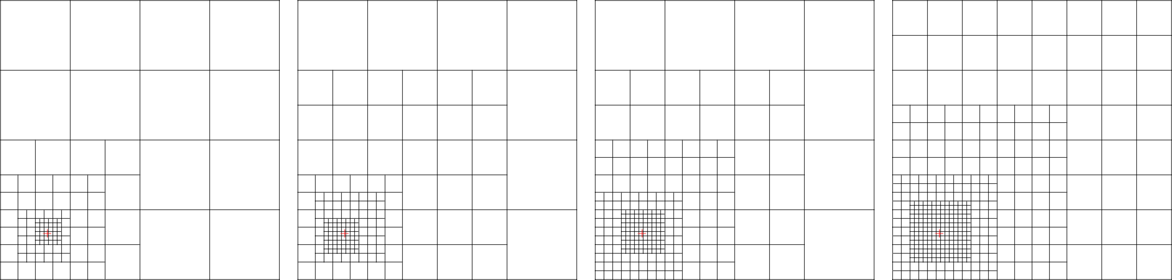
We call k the split distance factor. If you want to get a restricted quadtree, i.e., a quadtree in which the difference between the level of two neighbor quads is always 0 or 1, then k must be larger than 1:
Increasing the value of k means that quads are subdivided sooner, and appear smaller on screen. Hence you can tune the value of k to get a given resolution on screen. For instance, if each quad is rendered with a texture of TxT pixels, the projected size of these texture pixels on screen will be at most W/(2k.T.tan(fov/2)), where W is the screen width in pixels and fov is the field of view angle. The figure below gives an example of the result of this quadtree subdivision rule for several values of k above 1 (see also the "helloworld" example):
- Note:
- in practice the distance between a quad and the viewer also involves altitudes: d=max(min(|x-ox|,|x-ox-L|), min(|y-oy|,|y-oy-L|), z-groundz), where z-groundz is the height of the camera above the ground. Note also that this distance is computed in the local space, not in the deformed space (see above). For this the camera position is transformed from the deformed space to the local space.
Continuous level of details
When a quad is subdivided, popping can occur because the quad is suddenly replaced with 4 sub quads with new associated data. Hopefully, with k > 1, it is possible to do a progressive fading in of the new sub tile data, and a corresponding fading out of the old parent tile data. This replaces a sudden transition with a progressive blending, much less visible. This blending can be done as follows: at some point x,y in a quad (ox,oy,l), if the viewer is at (cx,cy), then the blending coefficient defined as:
can be used to mix the old parent tile data xparent and the new sub tile data xchild with:
Indeed when the viewer is at the minimal distance to the quad, dmin=kl, we get blend = clamp(-1/(k-1), 0, 1) = 0, and x = xchild. Inversely, when the viewer is at the maximal distance to the quad, dmax=(2k+1)l, we get blend = clamp(k/(k-1), 0, 1) = 1 and x = xparent. It is easy to compute the distances at which the clamping occurs, which gives the width of the transition region between blend = 0 and blend = 1. This width is equal to (k - 1)l, which shows that the larger is k, the larger is the transition region, and the less noticeable is the transition. This is illustrated below:
GLSL uniforms
The proland::Deformation::setUniforms method sets two uniforms that can be used to compute the above blending coefficient on GPU. The deformation.camera vec4 uniform stores the camera position, relatively to the quad lower left corner ox,oy and divided by the quad size l. The deformation.blending vec2 uniform stores k+1 and k-1. Using these uniforms, the blend coefficient can be computed as follows (the vertex coordinates are supposed to vary between 0 and 1 in the quad):
vec4 c = deformation.camera; // (cx-ox)/l, (cy-oy)/l, (cz-groundz)/l
vec2 k = deformation.blending; // k+1, k-1
vec2 v = abs(c.xy - gl_Vertex.xy);
float d = max(max(v.x, v.y), c.z);
float blend = clamp((d - k.x) / k.y, 0.0, 1.0);
Terrain classes
A terrain quadtree is represented with a tree of proland::TerrainQuad objects. Each object of this class provides the following fields:
-
parentgives a pointer to the parent quad. -
level,txandtygive the logical coordinates of the quad. -
ox,oxandlgive the physical coordinates of the quad. -
zminandzmaxgive the minimum and maximum elevations on the quad. -
childrenis an array of four pointers to the sub quads of this quad. It contains either four NULL pointers if the quad is a leaf, or four non NULL pointers to four sub quads (in the bottom left, bottom right, top left, top right order) if this quad is subdivided. -
visibleindicates if this quad is invisible, partially visible or fully visible from the viewer. This field is updated by the proland::TerrainQuad::update method.
The proland::TerrainNode class represents a terrain. It contains a pointer to the root of the terrain quadtree in proland::TerrainNode::root. It also contains the following fields:
-
splitDistis the split distance factor k used for distance based subdivision (see above). -
maxLevelis the quadtree level at which the subdivision must be stopped. -
deformis the terrain deformation used for this terrain (see above).
Internally, a proland::TerrainNode stores the current viewer position and the current view frustum planes. These current values can be retrieved in the local and deformed spaces (see Terrain deformation) with proland::TerrainNode::getDeformedCamera, proland::TerrainNode::getDeformedFrustumPlanes, and proland::TerrainNode::getLocalCamera. They are updated by the proland::TerrainNode::update method, which takes as argument a scene node defining the terrain position in world space (and from which the camera position can also be retrieved).
Terrain resource
A proland::TerrainNode can be loaded with the Ork resource framework, using the following format:
<terrainNode name="myTerrain" size="6360000" zmin="0" zmax="10000"
    deform="sphere" splitFactor="2" maxLevel="16"/>
This resource describes a terrain whose root quad has a size of 12720km x 12720km (12720 = 2*6360), whose elevations are between 0 and 10000m, using a spherical deformation (of course the length unit can be interpreted as you want). The terrain quadtree will be subdivided with a split distance factor k=2 (for a field of view of 80 degrees, and a viewport width of 1024 pixels. For a smaller field of view and/or a larger viewport, subdivisions will automatically occur at a larger distance, so that the size of a quad in pixels stays more or less the same), up to quadtree level 16 (included). Note: currently the optional deform attribute only supports the none and sphere values. In the case of a spherical deformation, the planet radius is set to size. The "terrain1" and "terrain2" examples illustrate how terrain nodes for flat and spherical terrains can be used.
Texture tile samplers
A proland::TerrainNode only stores the current quadtree of a terrain, subdivided based on the distance to the current viewer position. It does not store any data associated with this quadtree. Indeed the terrain or more generally the landscape data is produced by tile producers, and stored in tile storages managed by tile caches (see Producer framework). We therefore need a link between terrains and tile producers, so that producers are asked to produced new tiles when terrain quads are subdivided. This link is provided by the proland::TileSampler class.
A proland::TileSampler is associated with a single GPU tile producer. Its first role is to ask this producer to produce new tiles when a terrain quad is subdivided. Its second role is to set GLSL uniforms to allow a shader to access a texture tile in the tile storage used by this producer.
The first role is performed by the proland::TileSampler::update method. This method takes as argument the root of a terrain quadtree. It compares this quadtree with its previous value during the last call to this method. Then, for each new quad, it asks the associated producer to produce the corresponding tile, with getTile. Conversely, for each old quad (i.e., quads that are no longer part of the quadtree), it informs the producer that the corresponding tile is no longer used, by calling putTile. This ensures that the tile data is "locked" (see Tile cache) in the tile storage as long as the corresponding quad exists.
- Note:
- in fact the proland::TileSampler::update method returns a task graph containing all the tasks to produce the new tiles that must be produced. This task graph must be scheduled for execution in order to actually produce the tiles.
In practice it is not always necessary to produce a tile for each quad in the quadtree. For instance it is often sufficient to produce tiles for the leaf quads only, i.e., those that do not have sub quads, which are those that are effectively rendered. It is also common to produce tiles for the visible quads only, i.e., those that are fully or partially visible in the view frustum (see Terrain classes). In order to specify if a tile must be produced or not for a given quad, you can use the following configuration methods:
-
proland::TileSampler::setStoreLeaf indicates whether a tile must be produced or not for leaf quads. The default is true.
-
proland::TileSampler::setStoreParent indicates whether a tile must be produced or not for internal quads (i.e., non leaf quads). The default is true.
-
proland::TileSampler::setStoreInvisible indicates whether a tile must be produced or not for quads out of the view frustum. The default is true.
- proland::TileSampler::setStoreFilter adds an arbitrary tile filter to a list of filters. Each filter takes as argument a terrain quad, and returns whether or not a tile must be produced for it. If at least one filter decides that the tile must be produced, it will be produced.
Finally a TileSampler can be used in one of two modes: synchronous or asynchronous. In the default, synchronous mode, the update method uses an immediate deadline for the tasks needed to produce the tiles for the newly created quads. This means that the final frame will not be displayed until all the tiles are produced. When tile data must be loaded from disk, with a high latency, this can lead to visible freeze time between frames when the viewer moves.
This can be solved by using the asynchronous mode. In this mode the deadline for the tile production tasks is not set to the current frame. Thus a frame can be displayed even if some data is missing. In this case the first ancestor tile that is ready is used instead. This solves the latency problem, but degrades the quality when the viewer is moving fast, and gives visible popping artifacts when new data suddenly replaces the temporary low resolution data used while waiting it (this can even lead to gaps between terrain quads because then the quadtree used for display is not necessarily a restricted quadtree). In order to use this asynchronous mode, several options must be configured properly (the "earth-srtm-async" example illustrates this - note in particular the scheduler definition):
- proland::TileSampler::setStoreParent must be set to true. This is to ensure that we will find at least one ancestor whose data is ready when data for a tile is not yet ready.
- proland::TileSampler::setAsynchronous must be set to true.
- finally the ork::Scheduler used must support prefetching of any kind of tasks (both CPU and GPU). With a ork::MultithreadScheduler, this is only possible if a prefetch rate is specified, or if a fixed frame rate is specified.
- Note:
- You can mix TileSampler in synchronous mode with others using asynchronous mode. Hence some tile data can be produced synchronously while other data is produced asynchronously.
GLSL functions
As said above, the second role of a proland::TileSampler is to set GLSL uniforms allowing shaders to access a texture tile in the tile storage. This role is performed by the proland::TileSampler::setTile method, which takes as argument the logical coordinates of a tile. This method finds the location of this tile in the tile storage using findTile. It then sets the necessary GLSL uniforms to access the content of this storage slot from a shader. More precisely, if the requested tile is not found, its parent tile is looked for instead. If this parent tile is not found either, the parent of the parent tile is looked for, and so on until an ancestor of the requested tile is found. Then the necessary GLSL uniforms are set to allow shaders to access the sub part of the ancestor tile that corresponds to the requested tile.
In order to facilitate the use of texture tiles stored in tile storages, a tile storage is seen as a new kind of texture. By similarity with 1D, 2D, 2D array or 3D built-in textures, declared in GLSL with sampler1D, sampler2D, sampler2DArray or sampler3D, and used with the texture1D(), texture2D(), texture2DArray(), or texture3D() functions, we define a new samplerTile type and a new textureTile function for texture tiles stored in tile storages. Their definition is provided in the textureTile.glsl file.
Hence the tiles produced by a GPU tile producer p can be accessed as follows. We first create a TileSampler using this producer:
Ptr<TileSampler> u = new TileSampler("mySamplerTile", p);
The name "mySamplerTile" is the name of the samplerTile uniform that will be used in the shader to access the tiles. After the update method has been called, and after the tasks it returned have been executed, we can set the value of the "mySamplerTile" uniform to a specific tile, in the currently selected GLSL program (see ork::SceneManager::getCurrentProgram), with:
u->setTile(level, tx, ty);
Note the analogy with uniforms:
Ptr<Uniform3f> v = new Uniform3f("myUniform");
v->set(vec3f(1.0, 0.0, 0.0));
We can then render the corresponding quad. In the GLSL code, the tile can be accessed as follows (see the "terrain1" example):
#include "textureTile.glsl"

uniform samplerTile mySamplerTile;

void main() {
    ...
    vec4 v = textureTile(mySamplerTile, uv);
    ...
}
where the uv coordinates must vary between 0 and 1 in the quad (note that textureTile does not sample the border of the tile, if any, but only the interior part: the [0..1] range is mapped to the interior part of the tile).
- Note:
- if the GPU storage uses textures in
NEARESTmode, you can still perform a linear interpolation, in the shader, by usingtextureTileLinearinstead oftextureTile(this functions callstextureTilefour times and interpolates the results).
Tile maps
With the above method a samplerTile uniform can access only one tile at a time in a shader. You can of course declare several samplerTile in your shader, in order to access several tiles (in the same storage or not) simultaneously. Still, you are limited to select a fixed number of tiles, draw the corresponding quad, select another set of tiles, draw the corresponding quad, and so on for all quads. However it is sometimes necessary to have access to all the tiles of a producer (or of several producers) simultaneously. This can be done with tile maps: a tile map is an indirection structure on GPU that indicates, for each tile, where it is stored in a tile storage. Since a storage can store the tiles of several producers, you can then have access to all the tiles of these producers.
Usage
A tile map is used via a TileSampler. But it is important to know that a TileSampler used to access a tile map does not ask its associated producer to produce new tiles when quads are subdivided. In other words it can only access tiles, it cannot produce them. Hence it is necessary to use a "companion" TileSampler, without tile map but associated with a tile producer using the same tile storage, so that tiles can be effectively produced (in fact you can have several such "companion" samplers).
A normal TileSampler can be changed to one used to access a tile map as follows:
-
the first step is to declare the tile map in the GPU producer associated with the
TileSampler, with thetileMap="true"attribute (see GPUTileStorage). - the terrain node with which the "companion" samplers are associated must be declared with proland::TileSampler::addTerrain.
The tile map can then be used by calling the proland::TileSampler::setTileMap method, before using the textureQuadtree function in your shader (the "terrainShader.glsl" file in the "terrain5" example illustrates this):
#include "textureTile.glsl"

uniform samplerTile myTiles;

void main() {
    ...
    vec4 v = textureQuadtree(myTiles, xy, 0.0);
    ...
}
This function takes as argument x,y physical coordinates (varying between -L/2 and L/2, where L is the terrain size, i.e., the root quad size - see Producer framework; the third argument, here 0.0, is the producer id). It first finds the logical coordinates of the leaf quad that contains this point, and then uses the tile map to find the storage slot containing the corresponding tile. It finally returns the content of this tile at the requested location.
Algorithm
The first step finds the logical coordinates (level,tx,ty) of the leaf quad q that contains the point p of physical coordinates (x,y), assuming that the quadtree of size L is subdivided using the split distance factor k>1, with a viewer at (cx,cy). Once level is known, finding tx and ty is trivial (indeed tx = ⌊ 2level (x/L+1/2) ⌋, and similarly for ty). So the main problem is to compute level.
Let's note d=max(|x-cx|,|y-cy|) the distance between p and the viewer, and dq the (unknown) distance between the quad q and the viewer. We have dq < d < dq + L/2level. By hypothesis q is not subdivided, which implies
By hypothesis again the parent quad of q, noted r, is subdivided, which implies dr < kL/2level-1. With d r < d < dr + L/2level-1, this gives
We can then consider two cases: d < kL/2level-1, or d > kL/2level-1. In the first case we get with the first relation kL/2level < d < kL/2level-1, which gives level = ⌊ 1 + ln2(kL/d) ⌋. In the second case we get with the second relation kL/2level-1 < d < (k+1)L/2level-1. After some rewriting, this gives 1 + ln2(kL/d) < level < 1 + ln2(kL/d) + ln 2(1+1/k) < 2 + ln2(kL/d). We conclude that, in both cases, ⌊ 1 + ln2(kL/d) ⌋ ≤ level ≤ ⌊ 2 + ln2(kL/d) ⌋. So we compute level as follows: we first compute l = ⌊ 1 + ln2(kL/d) ⌋, deduce tx and ty from that, and test if the distance dq for this quad is less than kL/2l or not. Depending on the result, we know that level is either l or l + 1.
Once we have the logical tile coordinates, the second step must find where this tile is stored in the tile storage. This is the role of the tile map, which stores for each tile its slot in the storage (if present in the storage). In fact this map cannot have one entry for each potential tile: for a quadtree depth of 16, there are more than 416 potential tiles, i.e., more than 4 billions entries! A solution is to store an encoding of the quadtree on GPU. But finding a tile would require a full tree traversal. Another solution is to use a hash table on GPU, but it would be difficult to avoid collisions to ensure a maximum efficiency. We use another solution, which ensures a constant time access (no tree traversal, no collisions, small memory requirements). We use the fact that, at each quadtree level, the number of leaf tiles that can exist simultaneously is bounded and independent of the level.
A tile (l,tx,ty) cannot exist if its parent tile is not subdivided. If the viewer is at (cx,cy), the parent tile containing the viewer, (l-1, ⌊ 2l-1(cx/L+1/2) ⌋, ⌊ 2 l-1(cy/L+1/2) ⌋) is subdivided. And all tiles of level l-1 at a distance less than kL/2l-1 are also subdivided. This gives at most ⌈ k ⌉ such tiles around the parent tile, i.e., at most (2 ⌈ k ⌉+1)2 tiles of level l-1. Hence there are at most (4 ⌈ k ⌉+2)2 leaf tiles of level l at the same time, whatever the value of l. For k<2, this gives a tile map of size 102.depth, e.g., 1600 entries for a maximum depth of 16 (instead of 4 billions!).
In summary the CPU updates the tile map texture (at each frame, depending on the current cx,cy value) by storing for each leaf quad (l,tx,ty) its slot in the storage, in the texel of index
where
iy = ty - 2 ⌊ 2l-1(cy/L+1/2) ⌋ + ⌈ k ⌉
On GPU, once the (l,tx,ty) coordinates corresponding to the physical coordinates (x,y) have been found, the index i is computed, the value of the tile map at this index is retrieved to get the slot position, and finally the texture tile in this slot is sampled to get the result. The "terrainShader.glsl" file in the "terrain5" example contains a concrete implementation of the above algorithm.
Texture tile sampler resource
A proland::TileSampler can be loaded with the Ork resource framework, using the following format (see the "terrain1" example):
<tileSampler sampler="mySamplerTile" producer="myProducer"
    storeLeaf="true" storeParent="false" storeInvisible="false"/>
The sampler attribute specifies the name of the GLSL samplerTile uniform that will be set by setTile. The producer attribute is the name of a GPU tile producer resource. The storeLeaf, storeParent and storeInvisible attributes are options that specify when a tile must be produced for a given quad (see above). Using tileSamplerZ instead of tileSampler creates a sub class of TileSampler that reads back the tile data on GPU, supposed to be elevation tiles, and uses this data to update the zmin and zmax fields of terrain quads (see Terrain classes), as well as the terrain height under the camera, in proland::TerrainNode::groundHeightAtCamera.
A proland::TileSampler to access a tile map can be loaded as follows (see the "terrain5" example):
<tileSampler sampler="mySamplerTile" producer="myProducer"
    terrains="myTerrain1,myTerrain2,myTerrain3"/>
where the terrain attribute specifies the "companion" proland::TileSampler, indirectly via terrain node resources (you can specify at most 6 terrains).
Terrain tasks
Three ork::AbstractTask sub classes are provided to update a terrain node, to update a texture tile sampler, and finally to draw a terrain.
UpdateTerrainTask
The proland::UpdateTerrainTask simply calls the proland::TerrainNode::update method on a terrain. This updates the terrain quadtree, based on the new current camera position. A proland::UpdateTerrainTask can be created with the Ork resource framework, using the following format (the "helloworld" example illustrates this):
<updateTerrain name="this.terrain"/>
the name attribute specifies the terrain node that must be updated. It can have the following form:
-
name: in this case the terrain node is the terrain node resource whose name is name.
-
this.name,$v.name, flag.name: in this case the terrain node is the value of the field name (see Scene nodes) of the target scene nodethis,$v or flag (see Methods).
UpdateTileSamplersTask
The proland::UpdateTileSamplersTask simply calls the proland::UniformSamplerTask::update method on a set of texture tile samplers. This produces tiles for the new quads that appeared since the last execution of this task. A proland::UpdateTileSamplersTask can be created with the Ork resource framework, using the following format (the "terrain1" example illustrates this):
<updateUniform name="this.terrain"/>
the name attribute specifies a terrain node. It can have the following form:
-
name: in this case the terrain node is the terrain node resource whose name is name.
-
this.name,$v.name, flag.name: in this case the terrain node is the value of the field name (see Scene nodes) of the target scene nodethis,$v or flag (see Methods).
This task updates all the texture tile samplers that are associated with the scene node to which the Ork method that executes this task belongs. Indeed a scene node can have associated uniforms, including proland::TileSampler (a sub class of ork::Uniform).
DrawTerrainTask
The proland::DrawTerrainTask draws a mesh for each leaf quad of a terrain, using the currently selected program. Typically the mesh is a regular grid mesh, which is translated, scaled, and displaced by the GLSL program to draw each quad at the proper location in the terrain. Before drawing each quad, this task sets the uniforms that are necessary to deform the terrain quad with proland::Deformation::setUniforms. It also sets the uniforms necessary to access the tiles for this quad, using proland::TileSampler::setTile or proland::TileSampler::setTileMap (for each texture tile sampler associated with the scene node to which the Ork method that executes this task belongs).
A proland::DrawTerrainTask can be created with the Ork resource framework, using the following format:
<drawTerrain name="this.terrain" mesh="this.grid" culling="true"/>
the name attribute specifies a terrain node. It can have the following form:
-
name: in this case the terrain node is the terrain node resource whose name is name.
-
this.name,$v.name, flag.name: in this case the terrain node is the value of the field name (see Scene nodes) of the target scene nodethis,$v or flag (see Methods).
The mesh attribute is the name of a mesh resource (see Meshes). It specifies the mesh that is used to draw each leaf quad. It can have the following form:
-
name.mesh: in this case the mesh is the mesh resource whose name is name.mesh.
-
this.name,$v.name, flag.name: in this case the mesh is the mesh name of the target scene nodethis,$v or flag (see Methods).
The culling attribute specifies if all the leaf quads must be drawn, or only those that are in the view frustum. The default value is false, meaning that all leaf quads are drawn.
User Interface
Proland's whole interface is based on EventHandlers. To be user-friendly and quickly usable, it provides the basics for navigating through the large scenes that you can display in Proland.
The UI is split in two parts: The handling of events (for navigation, edition, ...), and the TweakBars, used to provide a visual help for these options. TweakBars are also EventHandlers, which enables them to use the keyboard, mouse and OpenGL events.
Default Handlers
View Handlers
When using a library such as Proland, a user-friendly navigation system is mandatory. Proland provides such a system, called proland::BasicViewHandler. Its behavior is quite straight-forward: When no other EventHandler catches the keyboard/mouse events, it uses them for navigation. The default navigation system is the following: PageUp and PageDown to move forward and backward (Z axis). The mouse left-click moves the camera along X and Y axis, while the right-click makes the sun turn around the SceneNode. CTRL + click turns the camera. The mouse wheel is the same as PageUp and PageDown.
proland::BasicViewHandler requires a proland::BasicViewHandler::ViewManager in order to work properly. This ViewManager provides acces to a ork::SceneManager, to a proland::TerrainViewController and to the screen to world transformation. BasicViewHandler directly computes the new position at each frame, and sets it in the TerrainViewController's camera position.
proland::TerrainViewController controls the camera position and orientation. The default implementation uses a flat terrain as root node, but Proland provides implementations for planets and cylinders as well.
BasicViewHandler can be loaded in the Ork Resource framework:
<basicViewHandler name="myViewHandler" viewManager="myWindow"
    next="anOptionnalEventHandler"/>
viewManager: the proland::BasicViewHandler::ViewManager object that handles the Navigation UI.next: an optional EventHandler that will receive the Events not captured by the view handler.
The "terrain3" example illustrates how this view handler can be used (especially when compared with the "terrain2" example) without Ork resources. The "ocean1" example illustrates how it can be used via Ork resources.
Event Recorder
The user might want to record a set of actions and to replay it later, or to create some videos of what he's doing in Proland. The proland::EventRecorder is able to do that. When pressing F12, it starts recording every events occuring until F12 is pressed again (all keyboard, mouse and OpenGL events are recorded together with the time at which they occured). Then, the user can replay them by pressing F11. When pressing Shift + F11, frames will be saved on the disk at a rate of 25 frames per second (using the original dates of each event, not the time during replay, which is perturbed by the time it takes to save frames on disk). This allows users to create a video afterwards. It is also able to save and load the recorded Events.
EventRecorder records the Events provided by a Recordable object. It works as a transparent layer on EventHandlers, i.e. it takes the place of an UI manager (a view handler for example), records all the events, and then passes them to the real UI manager, except when playing a video.
EventRecorder can be loaded in the Ork Resource framework:
<eventRecorder name="myEventRecorder" recorded="myWindow"
    videoDirectory="\home\myVideos\" cursorTexture"cursor" next="myBasicViewHandler"/>
recordedthe Recordable resource recorded by this EventRecorder.videoDirectorythe file name format to be used to save the video frames.cursorTexturea cursor texture to display the cursor position during replay.nextthe EventHandler that must handle the events recorded and replayed by this EventRecorder.
TweakBars
Apart from the controls, the Graphical part of the UI is also important, and the user must be able to quickly use the interface without knowing all the hotkeys used in the program. Plus, the information must be clearly visible, and easily managed for the developper. Philippe Decaudin developped a toolbar framework that has those qualities: AntTweakBars. Proland's toolbar are based on this framework.
To avoid displaying too many toolbars on the screen, Proland contains a proland::TweakBarManager, able to add the content from any poland::TweakBarHandler, and enable/disable them. When deactivated, they can themselves disable their linked EventHandler, if any (an editor for example). The TweakBarHandlers can be of three types: permanent (will always be activated), exclusive (they can't be enabled in the same time as other exclusive handlers) or regular (can be enabled/disabled at will).
As for EventRecorder, TweakBarManager is a transparent layer on a given UI manager. It is an EventHandler, thus able to catch events and to pass them to its TweakBarHandlers. Those will then determine if anything should be changed in the data they display; If it did, the manager will recreate the tweakbar with updated content.
Once again, the TweakBarManager can be loaded with the Ork Resource framework:
<tweakBarManager name="myTweakBarManager" minimized="false" next="myViewManager">
    <editor id="myEditor1" bar="myTweakBarEditor"
        exclusive="true" permanent="false" key="r"/>
<\tweakBarManager>
minimized: Determines if the TweakBarManager starts minimized or not.next: the EventHandler that must handle the unused events.bar: a TweakBarHandler that will add its content to the TweakBarManager.exclusive: Determines if the TweakBarHandler will be exclusive or not. Only one exclusive handler can be activated at the same time.permanent: Determines if the TweakBarHandler can be disabled.key: an optionnal hotkey to disable/enable the TweakBarHandler.
A few Tweakbars are available by default:
- proland::TweakResource: a flexible TweakBar directly described in the XML file, just like any other ork resource.
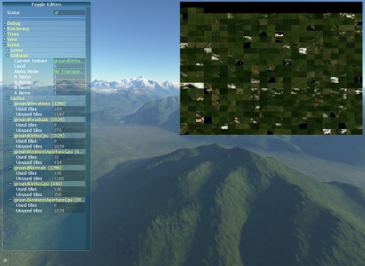
- proland::TweakSceneGraph: Enables to control the scene graph. Uses a proland::SceneVisitor object to browse the scene graph and display every nodes in the scene. Then, it allows the user to enable/disable almost any node.
- proland::TweakViewHandler: Controls a BasicViewHandler. Contains predefined positions accessible in one click. Also displays the current position.
The Proland examples illustrate how these tweak bars can be used (in particular the "edit1", "edit2", "edit3" and "edit4" examples). The figure below shows the interface of the proland::TweakSceneGraph: the tweak bar gives a tree representation of the scene graph, where each scene node can be expanded (allowing to show / hide this node, view its producers, invalidate their tiles, etc). This bar also gives a list of textures whose content can be displayed (on the right we see the texture used for the ortho producer tile cache). Finally it also shows statistics about the tile caches (capacity, number of tiles in use or not, etc).